
Build Your Own: Microarray Printer

PURPOSE:
Provide a DIY alternative to expensive commercial microarray solutions. Benefits of this system include high-throughput spotting and microarray customizability. It was initially built and documented by Joe DeRisi and team back in the late 90’s. One of these machines was assembled for the Fordyce lab at Stanford in 2016 and is documented here for others.
Introduction
As per Wikipedia:
A microarray is a multiplex lab-on-a-chip. It is a 2D array on a solid substrate (usually a glass slide or silicon thin-film cell) that assays large amounts of biological material using high-throughput screening miniaturized, multiplexed and parallel processing and detection methods.
In essence, if you want to do a high-throughput study with proteins, DNA, or other molecules, there’s a possibility that a microarray could fit your needs. In my opinion, the most significant advantage of using microarrays is being able to correlate a spatial signal to a known agent. It should also be noted that microarrays have been slowly phased out over the years due to advances in other technologies, but they still hold niche roles in science and medicine.
The microarray golden era was somewhat before my time, so I don’t know many details of how it rose and fell. From what I understand though, microarrays and microarrayers were solely a commercial product that were sold at somewhat exorbitant prices with limited customizability in the 90’s. Joe DeRisi worked with a few others in Pat Brown’s lab at Stanford to make an open-source system that could be replicated by other labs at a fraction of the price. They created a manual for assembly and developed software to operate the machine, which several groups used for their own systems. Given that many microarrays were nucleic acid based (ie the ViroChip), the use of these systems declined as alternative technologies such as sequencing and digital PCR became more prominent. For some time, I was fortunate enough to be able to operate Joe’s microarrayer at UCSF before it was disassembled and had the opportunity to construct one of the machines for the Fordyce lab at Stanford. Since most of the assembly material has been written previously, I’ll either be posting the original material, filling in some missing information or providing files that I created to supplement the existing material.
The microarrayer presented here has quite a few advantages and disadvantages that need to be considered before assembling. The greatest disadvantage by far is the sheer size of the machine. It sits on a large vibration-dampening table that’s about 6 feet wide and 4 feet long. In addition to that, it will need to be operated in a humidified environment in order to produce respectable arrays. (This latter constraint is eased by using droplet dispensers.) Traditionally, this environment was either a dedicated microarrayer room or a series of tarps hung from the ceiling. To control humidity, 3 or 4 large humidifiers were run throughout the print to maintain ~65% relative humidity. On the other hand, benefits include the ability to handle any full-skirt 384 plates, ability to handle any pins for spotting arrays, ability to print 30,000 spots on 261 slides in 20 hours, and flexibility in programming the arrays. In terms of throughput and customizability, it’s hard to beat. In terms of required spacing between spots, the limiting factor will be how large the pins spot the glass slide. Once the axes have been warmed up, the linear encoders prove to be very accurate.
Short Demo Video
The following video shows the print head printing spots onto 2x3 inch glass slides. In this example, the arrayer:
- Cleans the pins and returns to the source plate for the next set of samples.
- Draws samples from (4) adjacent wells on a 384 well plate.
- Prints (4) replicates of the samples on two regions of the glass slide.
- Advances to the next slide until all slides are arrayed.
- Returns to the cleaning station.
Microarrayer Assembly
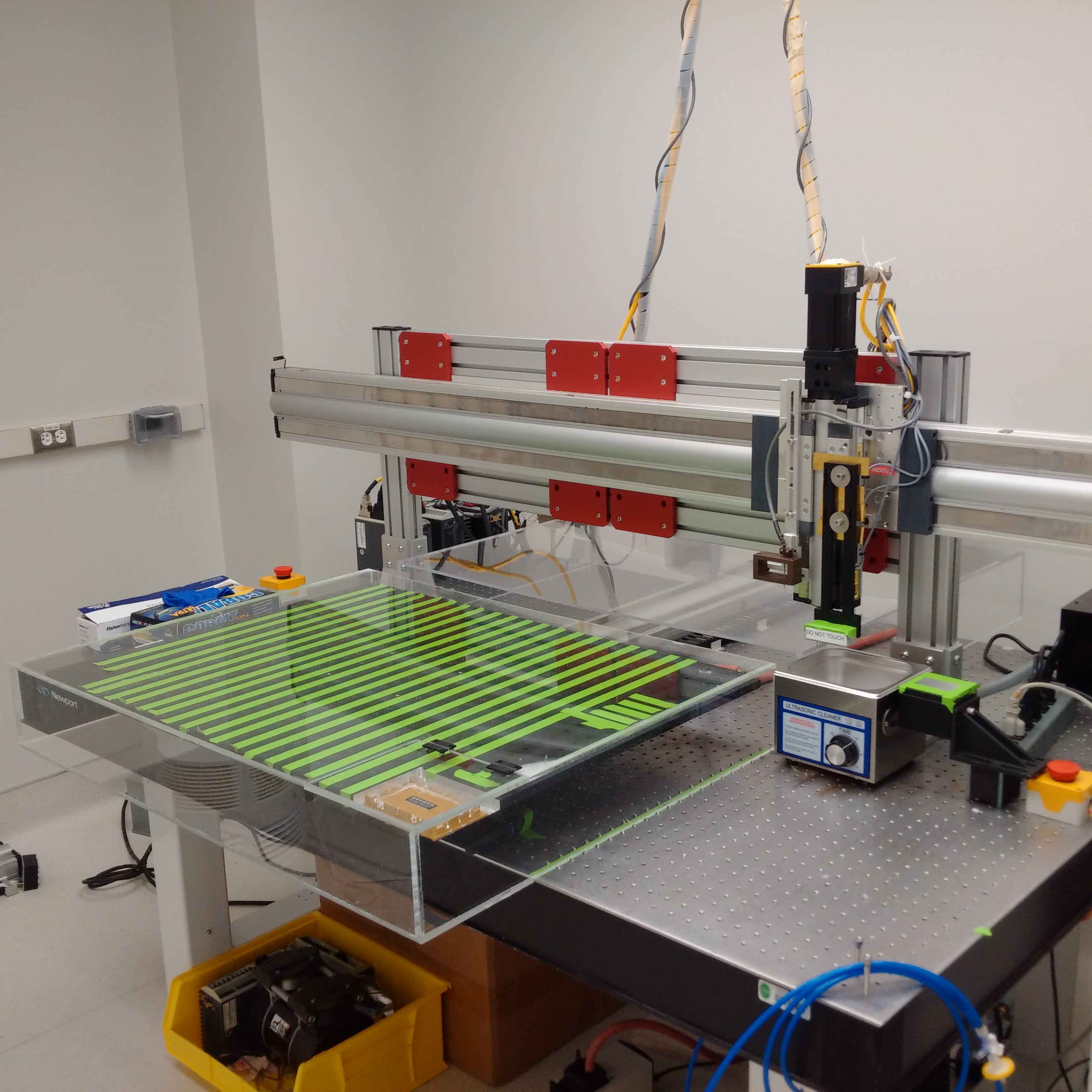
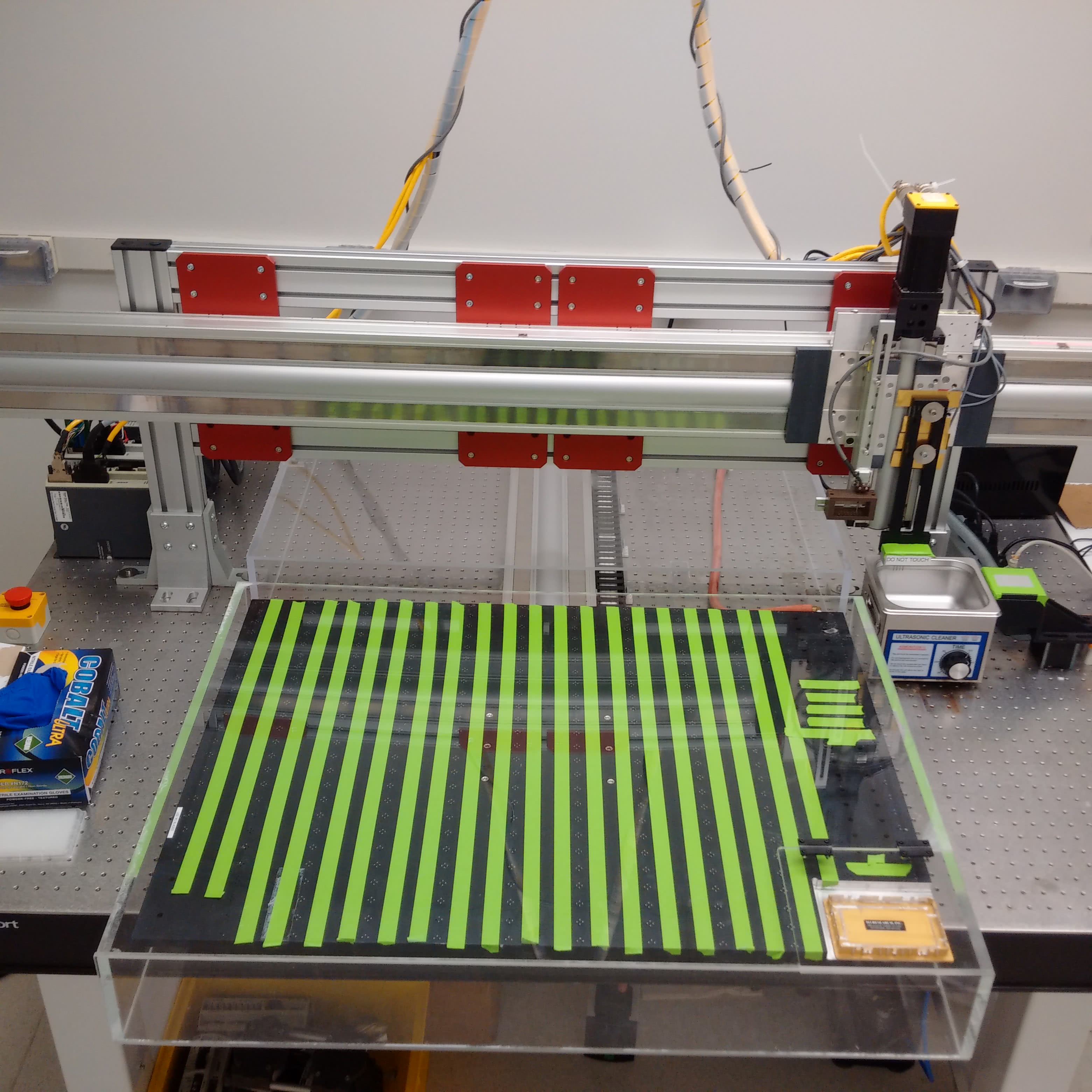
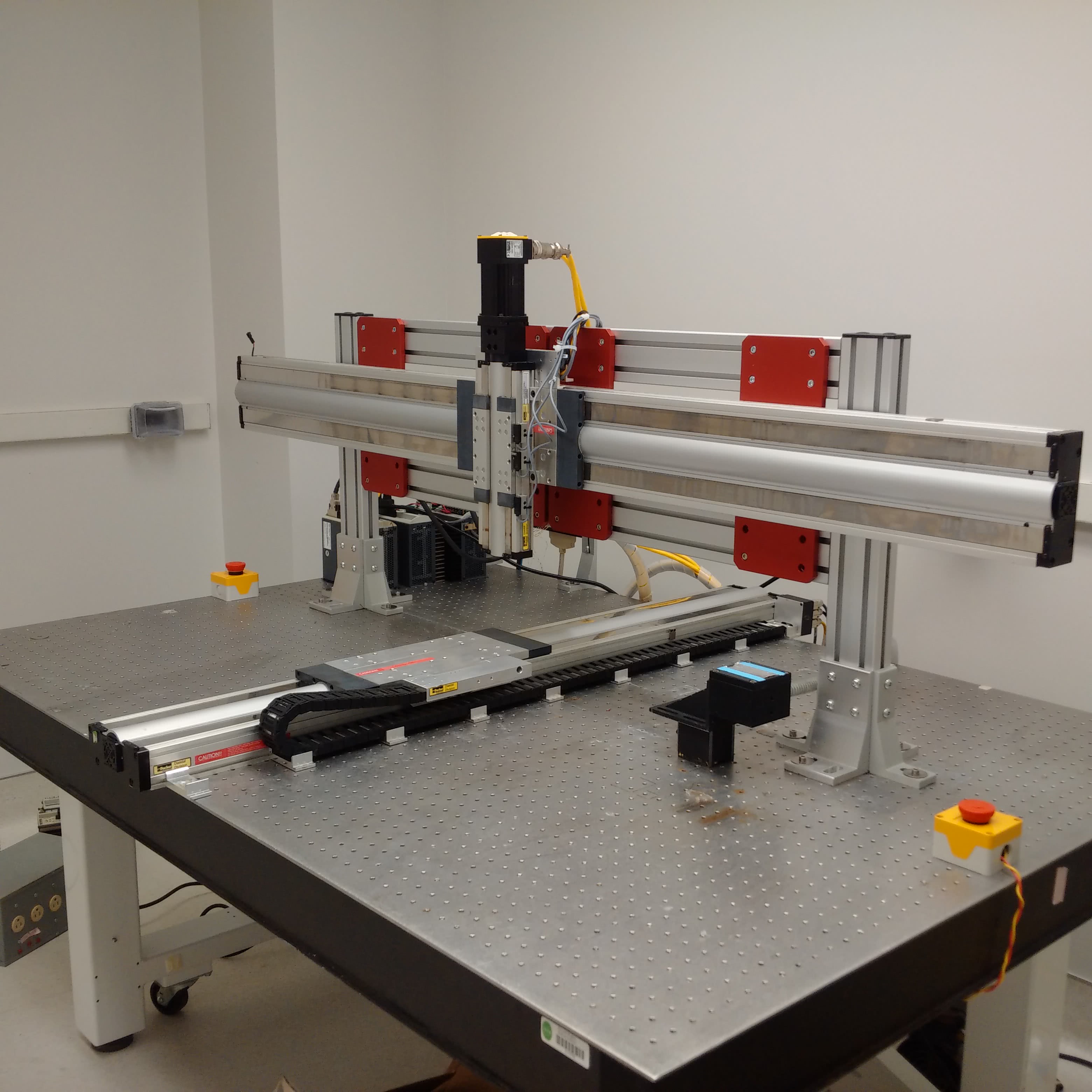
For assembling the machine, there are no resources better than the M-Guide, which was produced and revised by DeRisi’s team. Nearly every detail is covered - such as how to wire all of the axes or build the dust cover to protect the slides during a print. In the early 2000s, the whole build (including parts and tools) cost about $43,000, which was a fraction of the price of other options at the time. Since then, the price for the materials or commercial options have fallen. Maybe it was just luck, but I was able to find a nearly complete DeRisi style microarrayer selling for $4,000 at the time of writing this post.
I won’t go into detail about how to assemble it because it has already been written so well. However, I do want to note that some custom parts that I designed for the calibration arm or printing arm and printing block can be found in the Parts List and Files section below. Not listed there is information on how to make the slide platter. It may be best to contact Joe for that information, but it includes some specialized boring techniques that most machine shops don’t have from what I understand.
Microarrayer Software
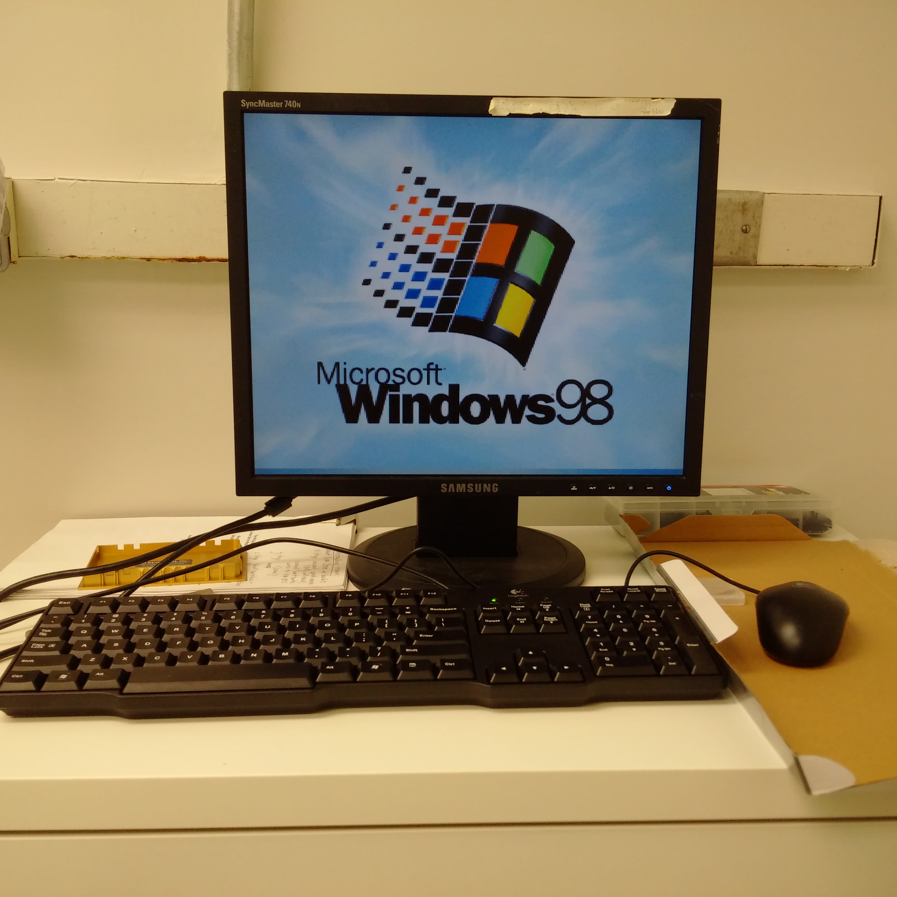
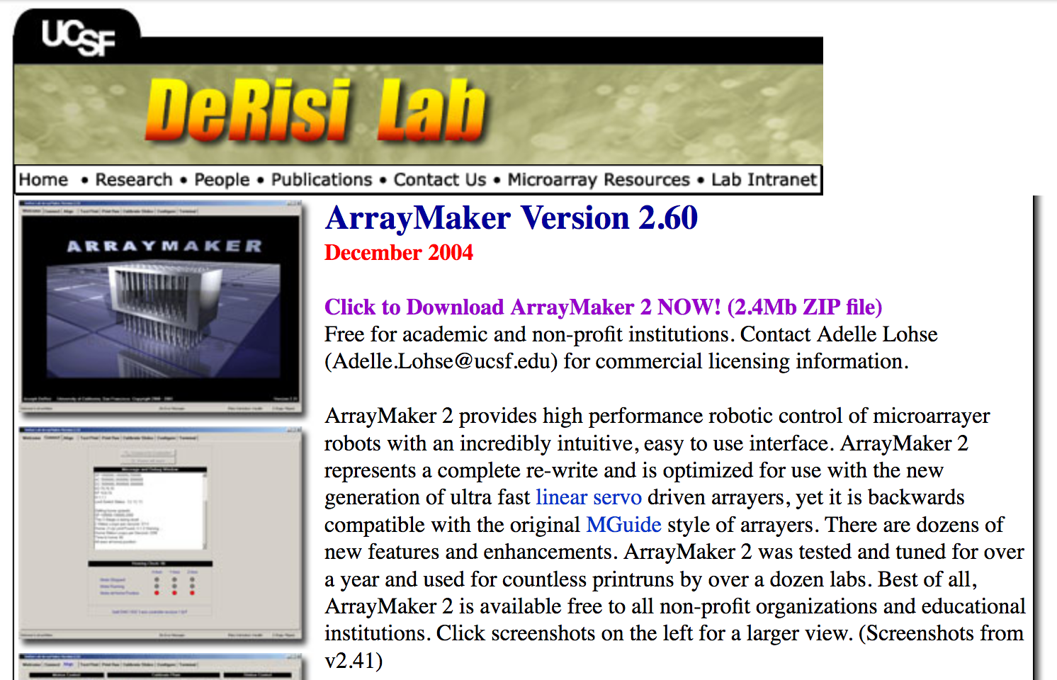
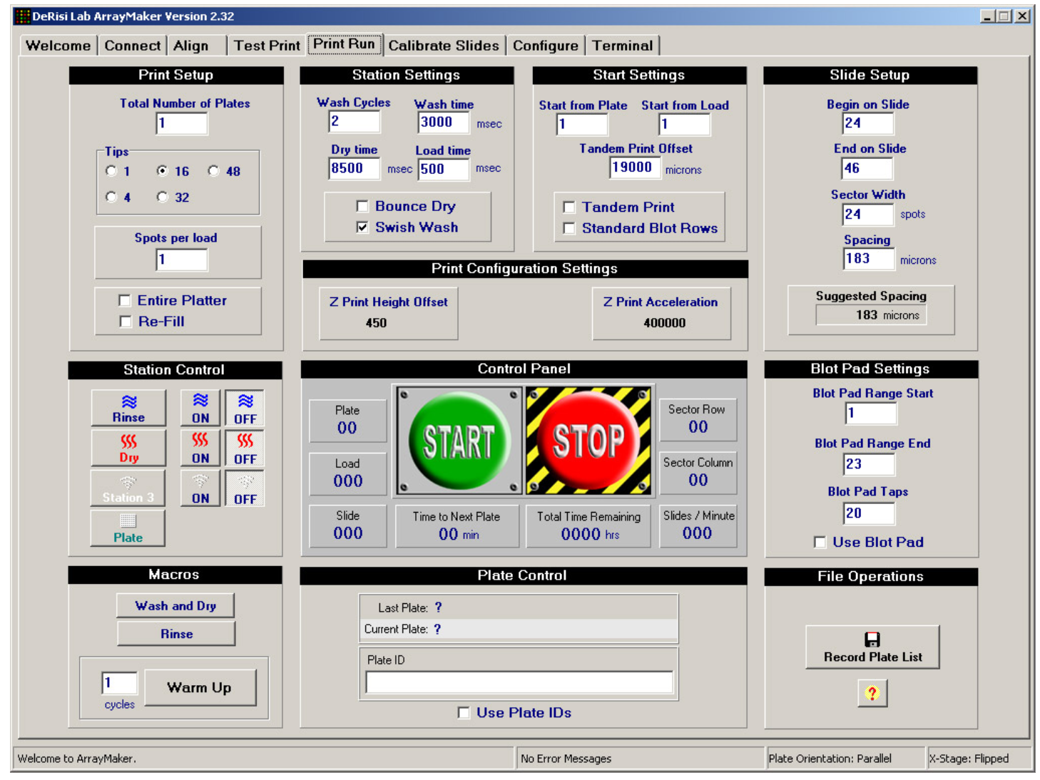
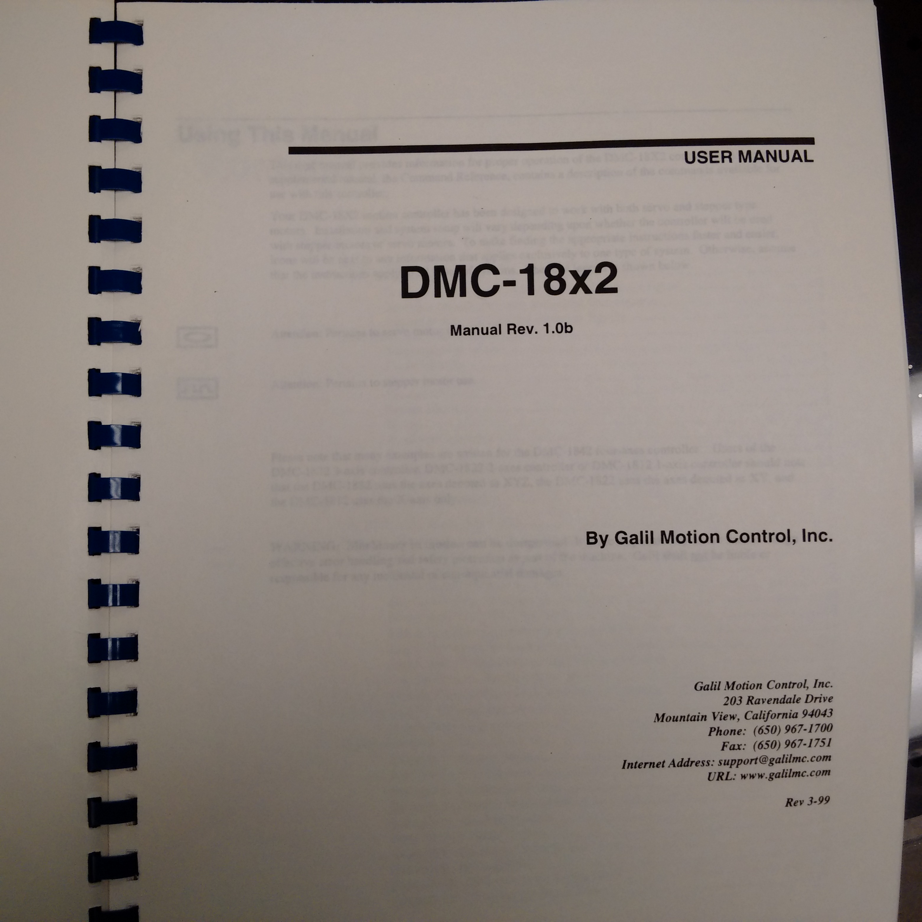
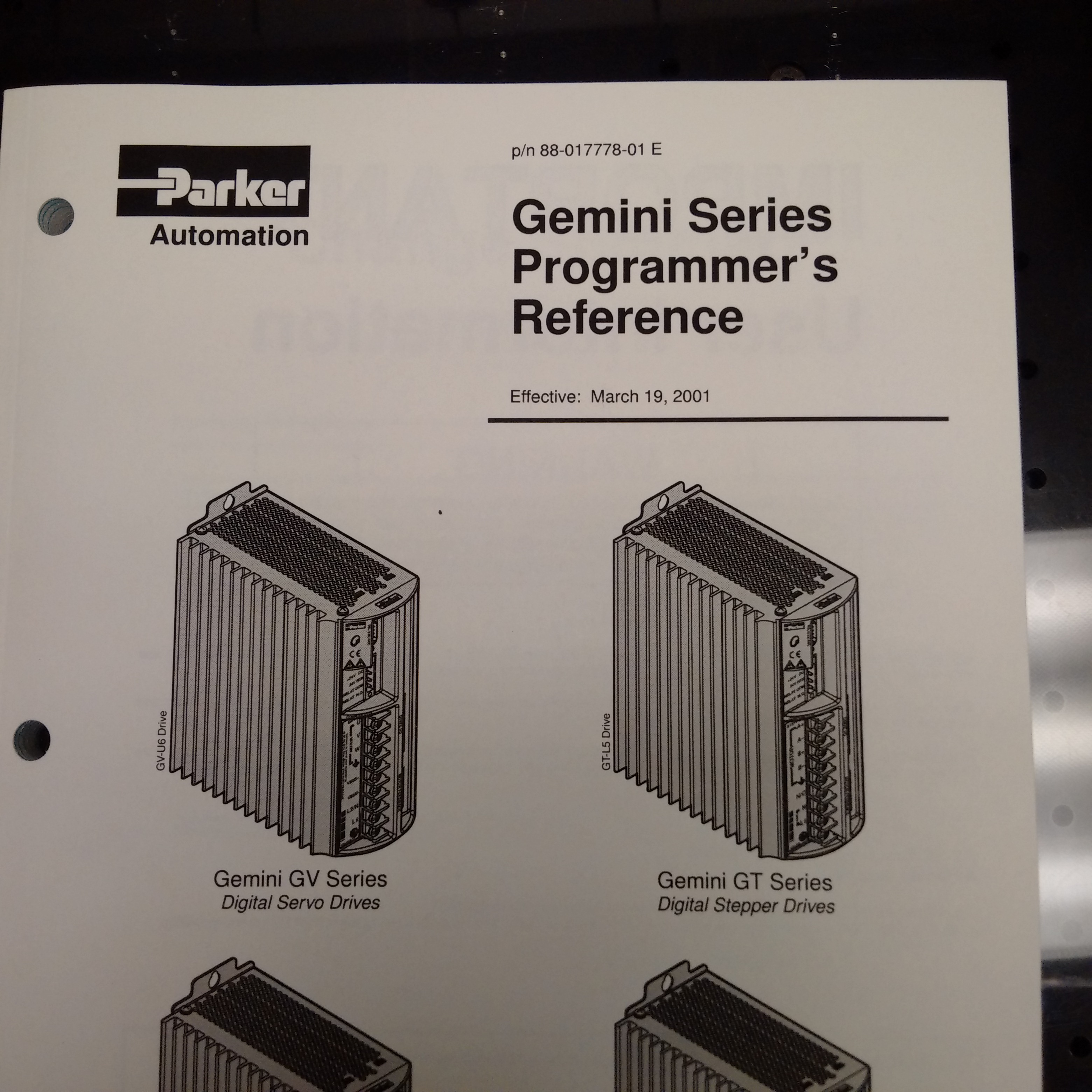
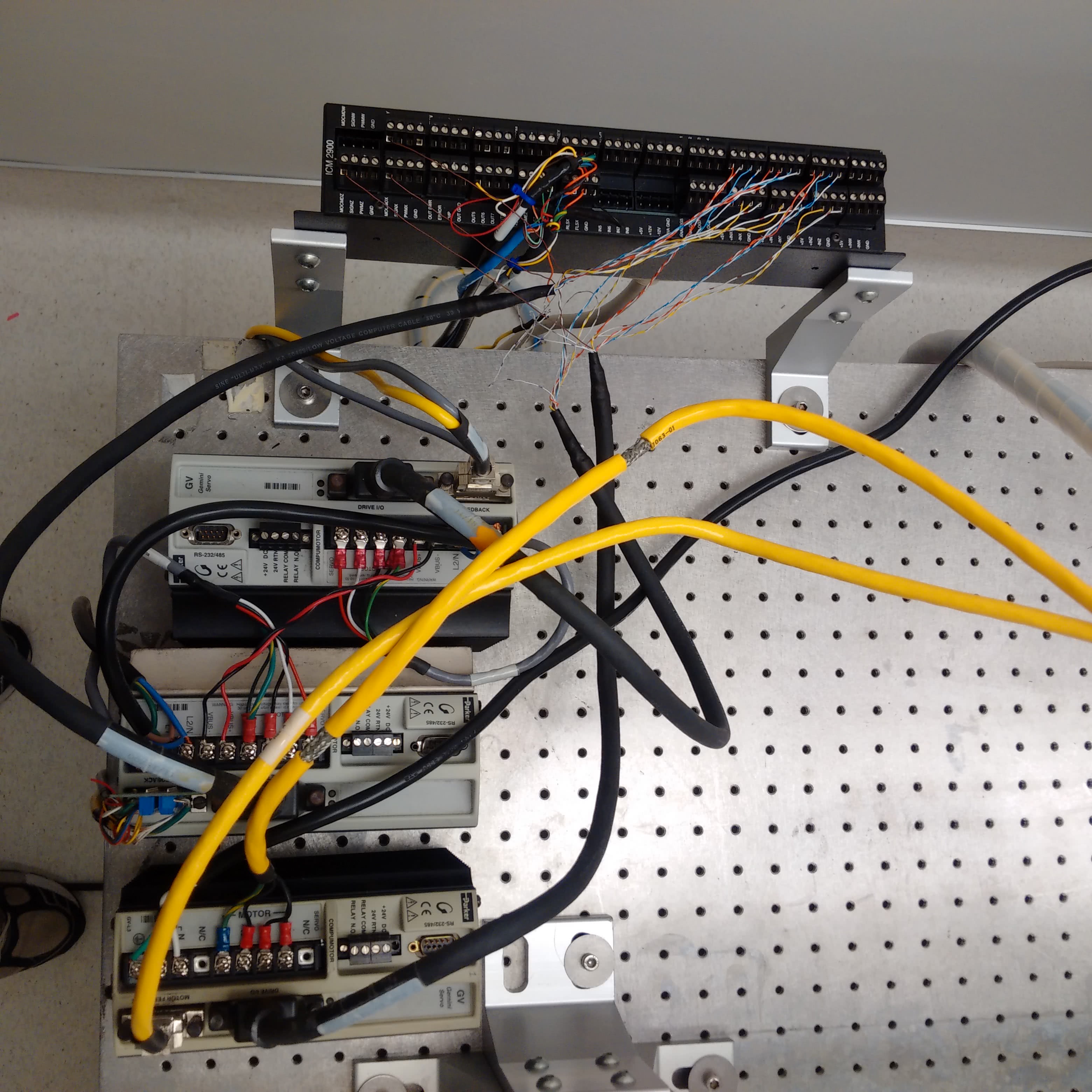
Unless you happen to have a PC happily running Windows 98, it might be best to not dwell here. Although the DeRisi group did produce software to control the microarrayer, it has aged and it might be best to rewrite a program for yourself. The ArrayMaker software and operating manual was pulled from an archived version of Joe’s website and can be found in the Parts List and Files section below. This software isn’t the latest version (2.78), but it could still prove to be a useful resource regardless. Possibly, the most important thing to note here is that most of the instructions programmed will either be for the Galil DMC-18x2 motion control card or the Gemini servo controllers. Images of their reference guide are posted above.
Parts List and Files
Guides
DeRisi M-Guide
DeRisi Printing Guide
Puccinelli Printing Guide
Software
As mentioned previously, the control software produced by the DeRisi group is out-of-date and is listed here for reference only or if you happen to have a functioning Windows 98 computer.
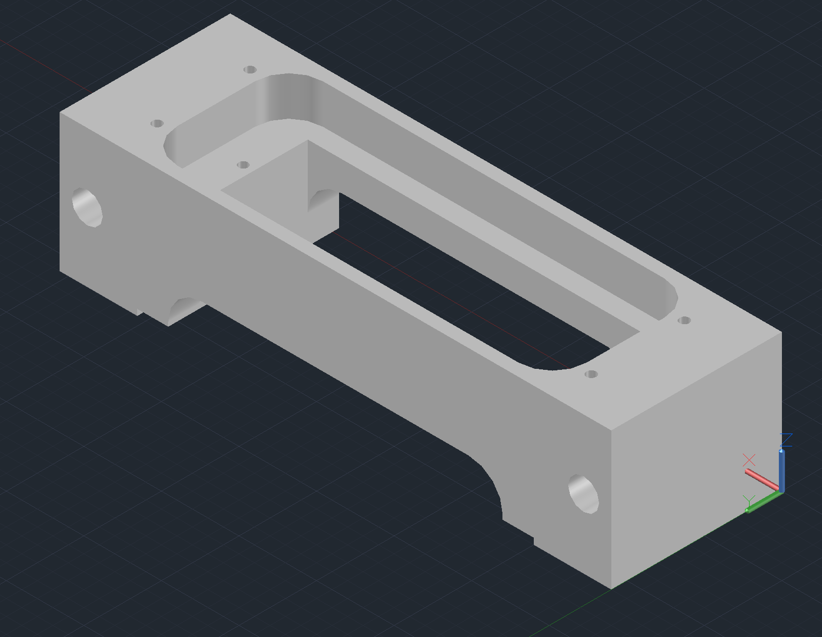
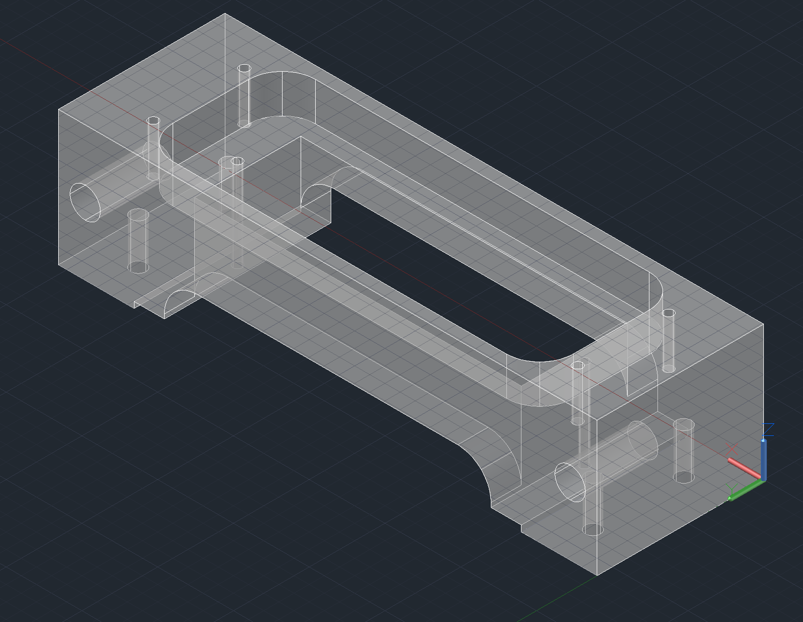
Arrayer CAD Files
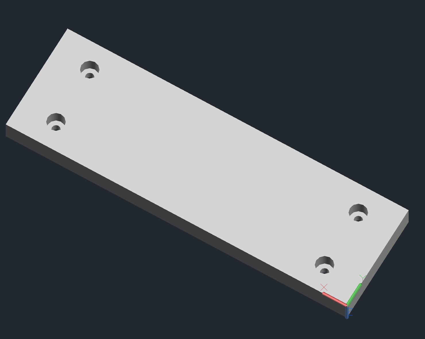
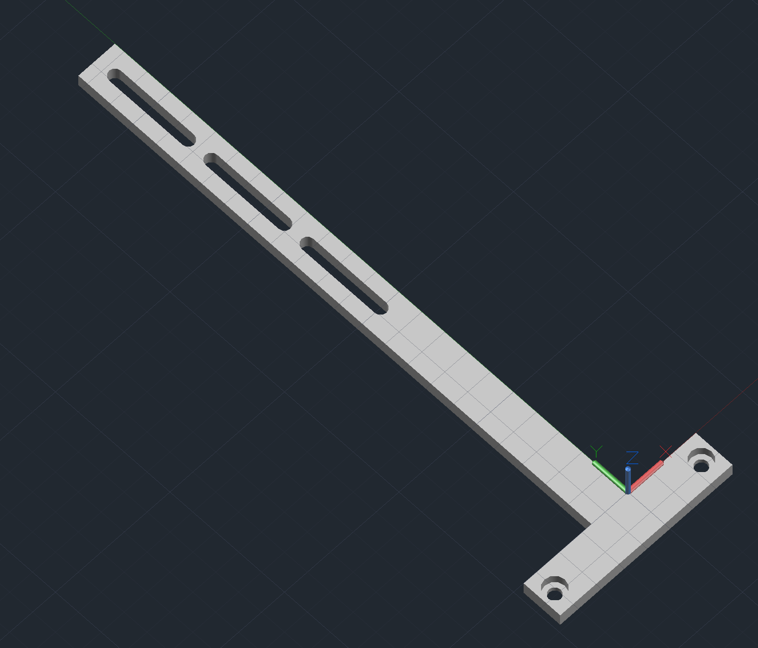
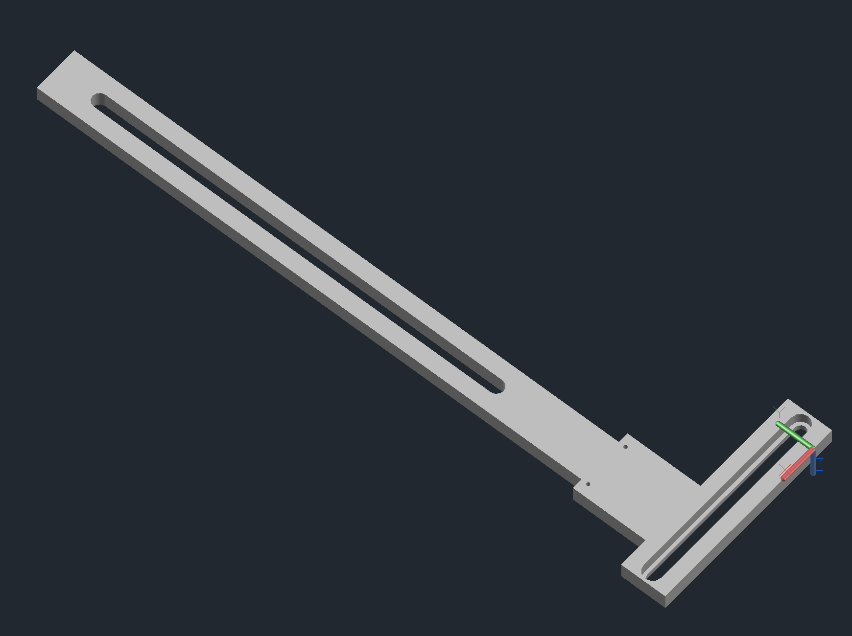
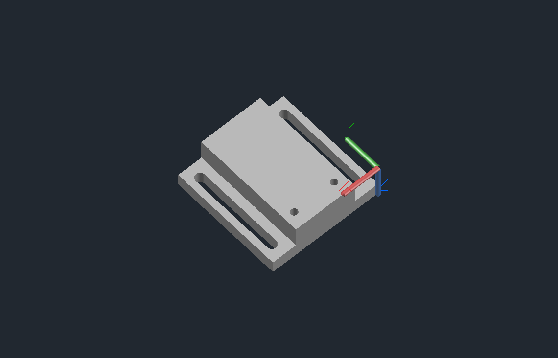
Provided here are a series of custom parts that I designed to set up the arrayer at Stanford. These are virtually identical to the parts that were used by the DeRisi lab.
Download AutoCAD and SolidWorks drawings here!
Arrayer CAD Notes
Some things to note that might not be obvious from the design files:
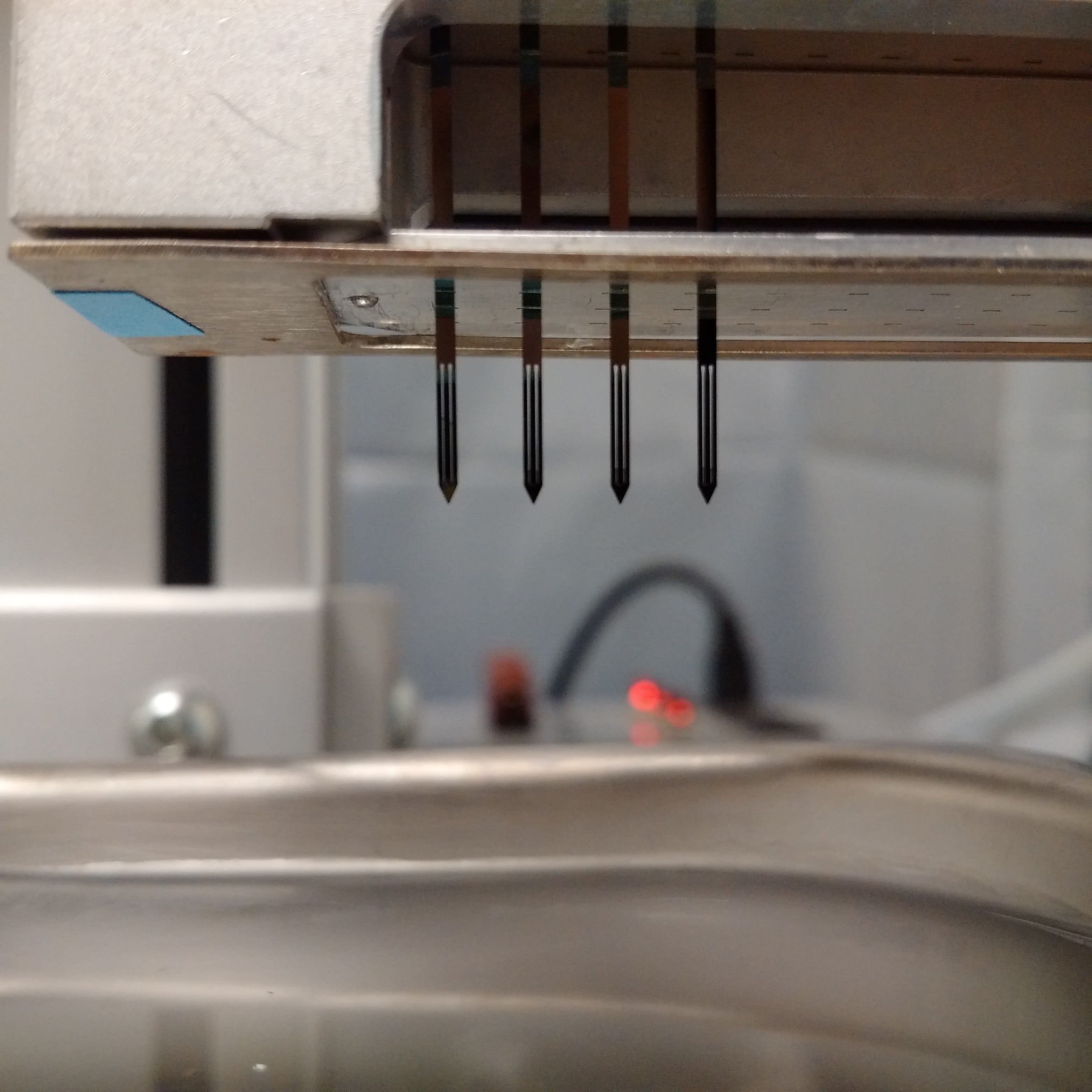
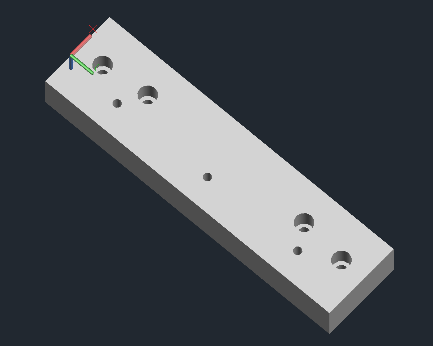
Pin Block Body
- Will need some 1.5mm dowels press fit in the top and lower inner lip to support the colimiter plates that align the silicon pins.
- Will need (4) 2.5mm diameter x 5mm length magnets press fit into the bottom to mount the magnetic plate that holds the lower colimiter plate.
- Will need top (4) holes tapped for M2 to mount the head.
- Will need back (2) holes tapped for M6 to mount to printing arm.
Pin Block Head
- Will need a soft and compressible foam cushion that fills the void between the pins and the head. This cushion protects the pins from vibrations and acts as a spring to ensure contact with the glass slide while printing.
Colimiter Plates
- Will be fairly expensive to machine due to the size of the features and the tight tolerances. These were initially designed to work with the Parallel Synthesis Technologies SMT pins, but may be compatible with others.
Printing Arm
- Attaches the pin block body to the z-axis.
Calibrator Arm
- Attaches the calibrating pin and mechanical switch to the z-axis.
- Will need to be tapped for M2 to attach the calibrator mount.
Calibrator Mount
- Attaches the mechanical switch to the calibrator arm.
- Will need to be tapped for M2 to attach the mechanical switch.
Delrin Block
- Couples the slide platter to the x-axis.
- Will need to be tapped for M6 for the holes that don’t attach to the x-axis.
Comments
Bettina
Awesome content, keep up good work
reboots
Robert, thanks for publishing this information. I purchased two sets of this same DeRisi microarrayer hardware (without the tables) at auction from the University of Texas, with the intention of recycling it to construct a CNC machine tool. It was very interesting to find this background on the DeRisi microarrayer system, and the M-Guide is a big help in rebuilding the assemblies and cabling.
Robert Puccinelli
@reboots - I’m glad that you found this information useful. Feel free to reach out to me directly if you have questions about your hardware and I’ll see what I can do (email to the left). Those servos are overkill for a microarrayer and would probably serve a CNC more appropriately.
Leave a Comment
Comments are moderated. Email won't be published. All fields are required. *