
Guide: Flashing the P1 (FT231X)
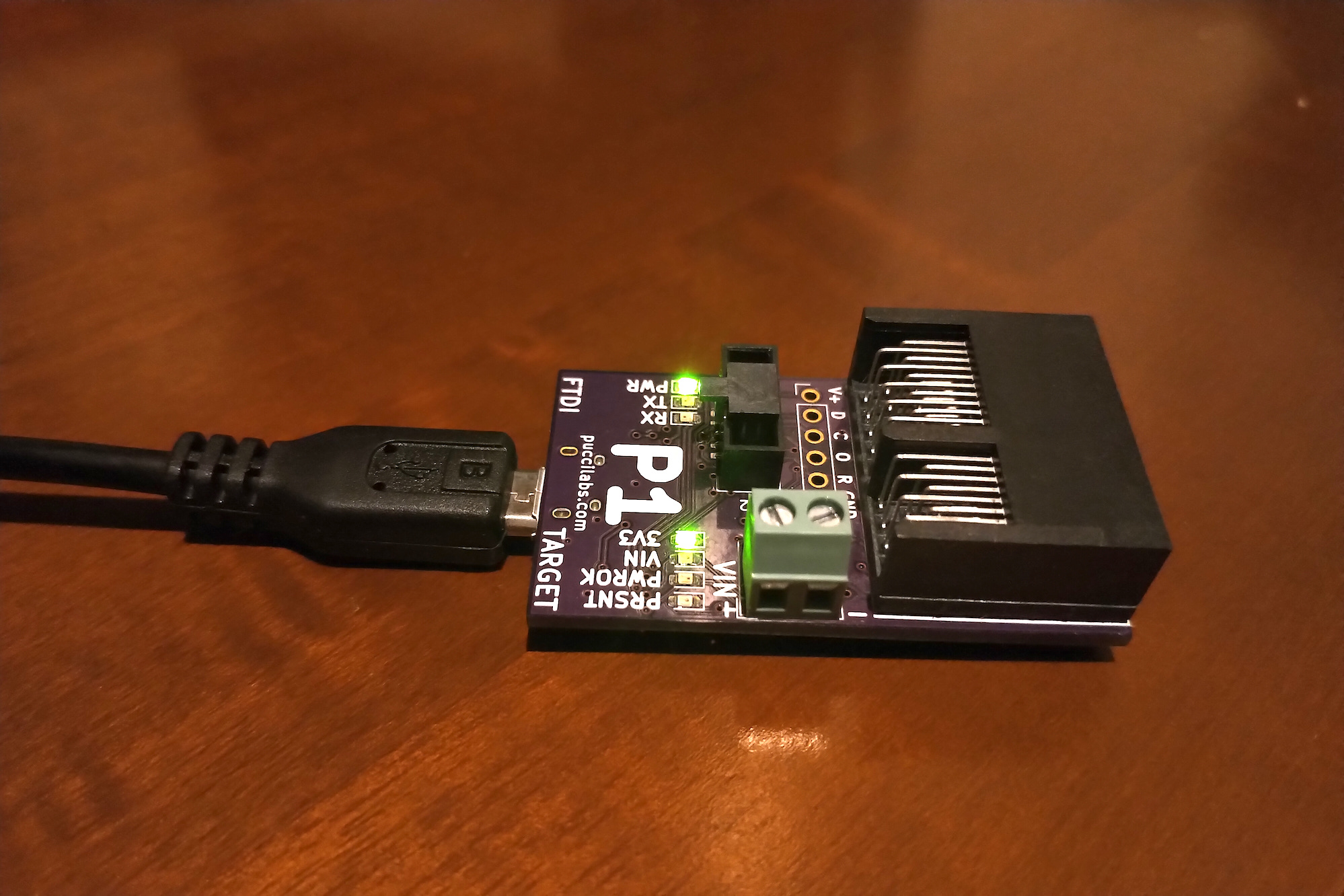 P1 Programmer
Overview
The objective of this guide is to demonstrate how to program the P1 Programmer using pyftdi with a Linux based machine. Once it has been programmed, it can then be used to interface with other Vespucci modules for testing and flashing.
Materials Used
- P1 Programmer
- Micro USB Cable
- Raspberry Pi
Guide
FT231X Description
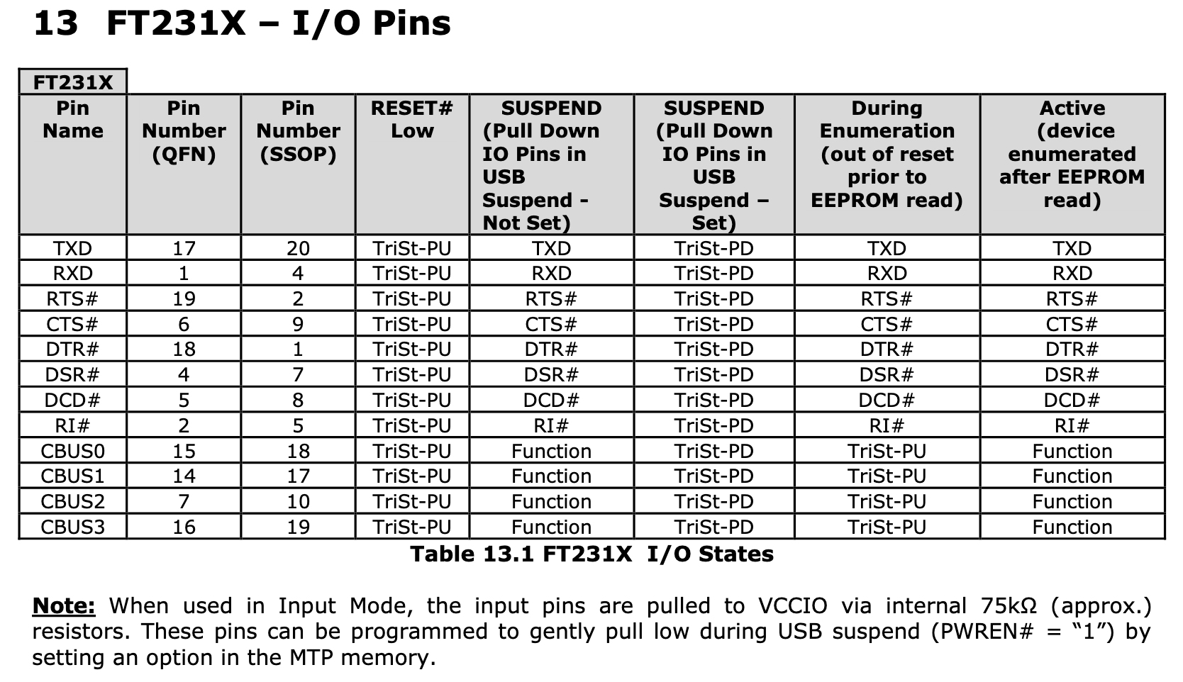
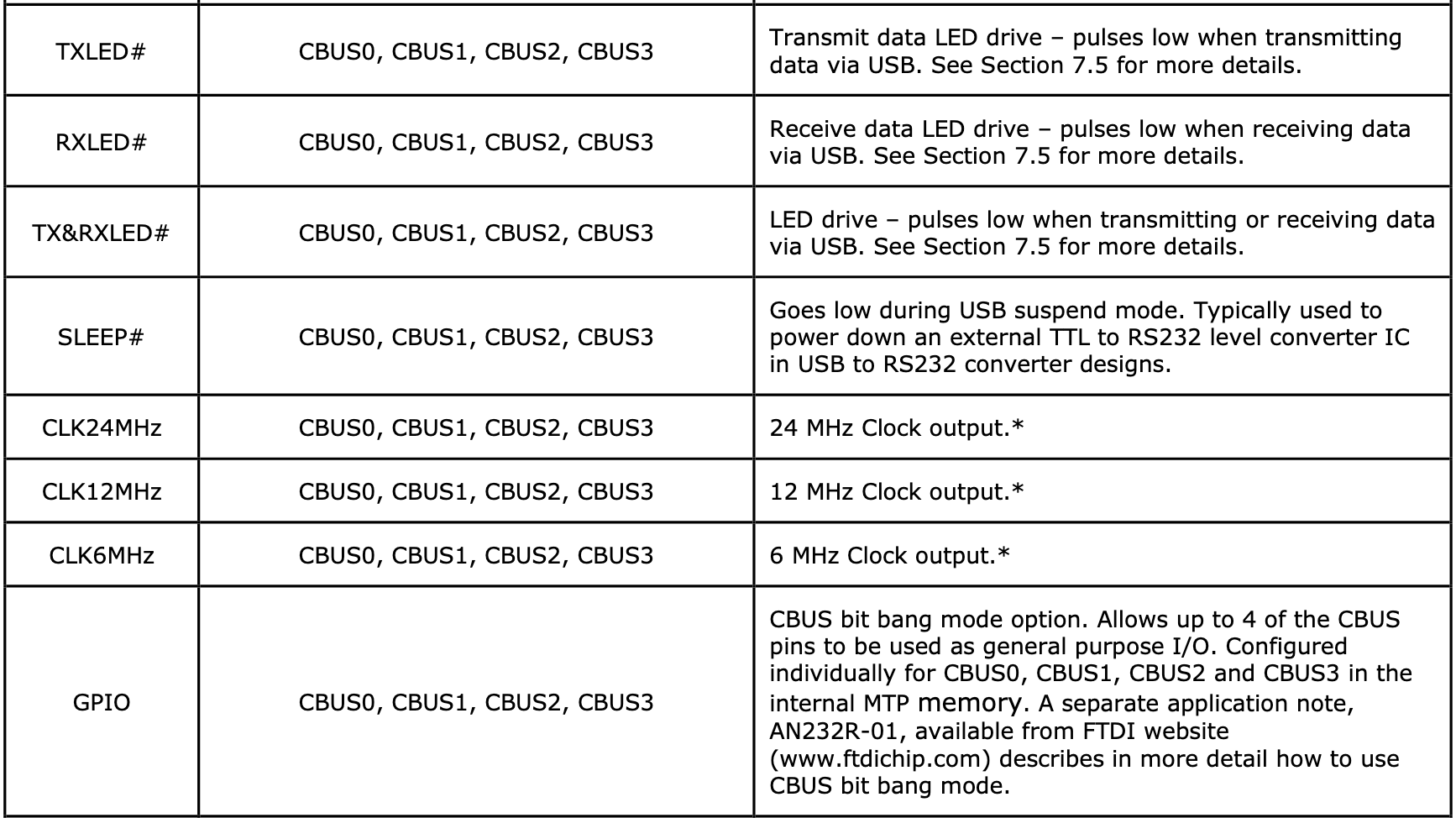
The P1 programmer utilizes the FT231X to interface with UART devices with full handshake via USB while also providing four GPIO pins (CBUS) that are independent of the UART interface. FTDI chips typically utilize the virtual com port driver (VCP) to bridge USB to UART, but programmable control of the CBUS requires the use of FTDI D2XX driver. The figures below are from FTDI Application Note 184, which describes the various I/O states, and from the FT231X datasheet to describe the potential CBUS functions of interest. In particular, our design will utilize the TX LED, RX LED and GPIO functions.
P1 Pinout Description
Vespucci modules are designed to utilize most of the full UART signals, so all lines except for the DSR will be used by the FT231X. The following figure describes the pinout for the FTDI IC. Of note, the only pins that require programmatic control are CBUS0 and CBUS3. CBUS0 serves as a power on signal to wake attached modules. CBUS3 serves as a signal to power the 3V3 bus for attached modules. The bus power signal can either be sent by the FTDI chip or from an attached Black Magic Probe. A more complete schematic can be found in the PCB GitLab repo.
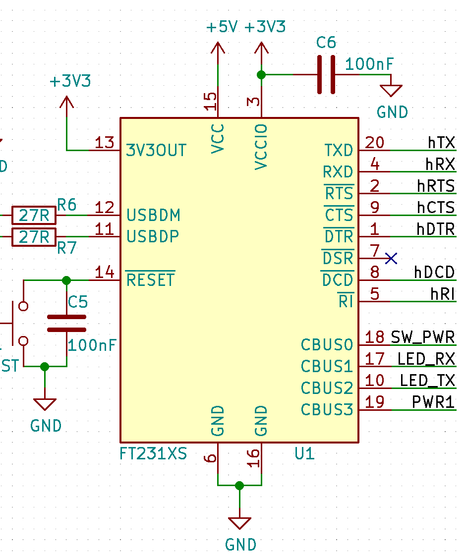 FT231X Pinout on the P1 Programmer.
pyftdi Installation
The programmer will be programmed and controlled with pyftdi on Linux, which provides a Python wrapper for an open source variant of the FTDI D2XX driver. I’m using pyftdi because that is the first library that worked for me and it seems to be actively updated at the time of writing. With respect to other systems, I ran into permission issues when using OSX where serial access was restricted and I couldn’t solve the problem. Windows was providing segfault issues and Ubuntu on a hypervisor or WSL had trouble finding the programmer or ran into segfault issues as well. I did find that using a pure Linux OS worked without an issue - in this case, a Raspberry Pi 3B with a Debian image. The following instructions are more or less copied from the pyftdi installation guide. Another benefit of pyftdi is that the EEPROM can be flashed without needing to use FTDI’s FT_Prog utility. This will allow us to use a custom VID PID code when we’re able to get one without needing to recompile a Windows driver.
- Install Python3, required modules and the libusb driver. Create a udev rule to escalete FTDI device permissions.
sudo apt-get install python3, python3-pip, python3-venv, libusb-1.0
sudo nano /etc/udev/rules.d/11-ftdi.rules
In the 11-ftdi.rules, enter the following and save the file:
SUBSYSTEM=="usb", ATTR{idVendor}=="0403", ATTR{idProduct}=="6015", GROUP="plugdev", MODE="0664"- Reload udev rules and add current user to the group.
sudo udevadm control --reload-rules
sudo udevadm trigger
sudo adduser $USER plugdev
newgrp plugdev- Create a Python3 virtual environment and install packages.
mkdir programmer & cd programmer
python3 -m venv venv_programmer
source venv_programmer/bin/activate
pip install pyftdi
FT231X Programming
Some of the settings on the FTDI chip should be changed on the P1 such as the CBUS pins as outlined above and the maximum current, which is set to 300mA for driving downstream modules. A config that is ready to go can be downloaded from this link and can be programmed with the following command.
python ftconf.py ftdi:///1 -l -i p1_config.ini -uThe ftconf.py script can be found in venv_programmer/bin/ftconf.py.
The device hexdump isn’t particularly necessary, but I’ll post it here in the event that it’s useful for someone later on. The last string, PL5J9KNY, is the device serial number and should be varied between devices.
python ftconf.py ftdi:///1 -x

000000   00 00 03 04 15 60 00 10 80 96 0c 00 00 00 a0 14   .....`..........
000010   b4 1c d0 12 00 00 00 00 00 00 08 01 02 08 00 00   ................
000020   00 00 00 00 00 00 00 00 00 00 00 00 00 00 00 00   ................
000030   00 00 00 00 00 00 00 00 00 00 00 00 00 00 00 00   ................
000040   00 00 00 00 00 00 00 00 00 00 00 00 00 00 00 00   ................
000050   00 00 00 00 00 00 00 00 00 00 00 00 00 00 00 00   ................
000060   00 00 00 00 00 00 00 00 00 00 00 00 00 00 00 00   ................
000070   00 00 00 00 00 00 00 00 00 00 00 00 00 00 00 00   ................
000080   4a 36 b5 c9 01 00 b9 41 6a 31 40 00 00 00 00 00   J6.....Aj1@.....
000090   00 00 00 00 44 33 53 44 4f 43 5a 44 00 00 00 00   ....D3SDOCZD....
0000a0   14 03 50 00 75 00 63 00 63 00 69 00 4c 00 61 00   ..P.u.c.c.i.L.a.
0000b0   62 00 73 00 1c 03 50 00 31 00 20 00 50 00 72 00   b.s...P.1. .P.r.
0000c0   6f 00 67 00 72 00 61 00 6d 00 6d 00 65 00 72 00   o.g.r.a.m.m.e.r.
0000d0   12 03 50 00 4c 00 35 00 4a 00 39 00 4b 00 4e 00   ..P.L.5.J.9.K.N.
0000e0   59 00 00 00 00 00 00 00 00 00 00 00 00 00 00 00   Y...............
0000f0   00 00 00 00 00 00 00 00 00 00 00 00 00 00 a6 0a   ................
To set your own parameters, you can modify the following command. Append -v to the end to see what the configuration result is or append a -u to the end to upload the configuration to the FTDI chip.
python ftconf.py ftdi:///1 -m PucciLabs -p 'P1 Programmer' -c cbus_func_0=GPIO -c cbus_func_1=RXLED -c cbus_func_2=TXLED -c cbus_func_3=GPIO -c power_max=300There you go! You have now programmed the P1 Programmer so that it is ready to use with other Vespucci modules.
Leave a Comment
Comments are moderated. Email won't be published. All fields are required. *